

Calibration
Learn how to fine-tune and calibrate your SenseAi device to accurately detect your machine states, thresholds, and vibration patterns for optimal OEE reporting.
Overview
The SenseAi devices come preconfigured and calibrated using data collected from similar machines. However, fine-tuning the parameters and calibrating the device for your specific machine and mounting location ensures the best detection accuracy.
Even identical machines of the same model and age can exhibit different vibration signatures, so calibration helps SenseAi adapt precisely to your environment.
Why calibrate?
- Improve detection accuracy for your specific machine
- Eliminate false positives/negatives
- Optimize OEE and utilization calculations
- Adapt to your unique mounting location and environment
When to calibrate:
- After initial installation
- When moving the sensor to a different location
- If detection accuracy seems off
- After significant machine maintenance or changes
Estimated time: 15-30 minutes
Prerequisites
Before starting calibration, ensure:
- SenseAi device is installed and powered on
- Device is connected to the internet (stable cyan or orange LED)
- You have access to the IoTFlows Dashboard
- Machine is operational (can run and stop on demand)
- You can observe both idle and running states during calibration
Step 1: Access Calibration Interface
When your SenseAi device is powered on and placed on the machine, follow these steps:
- Go to your IoTFlows Dashboard
- Select the machine of interest
- Tap on the SenseAi device image to open the calibration page

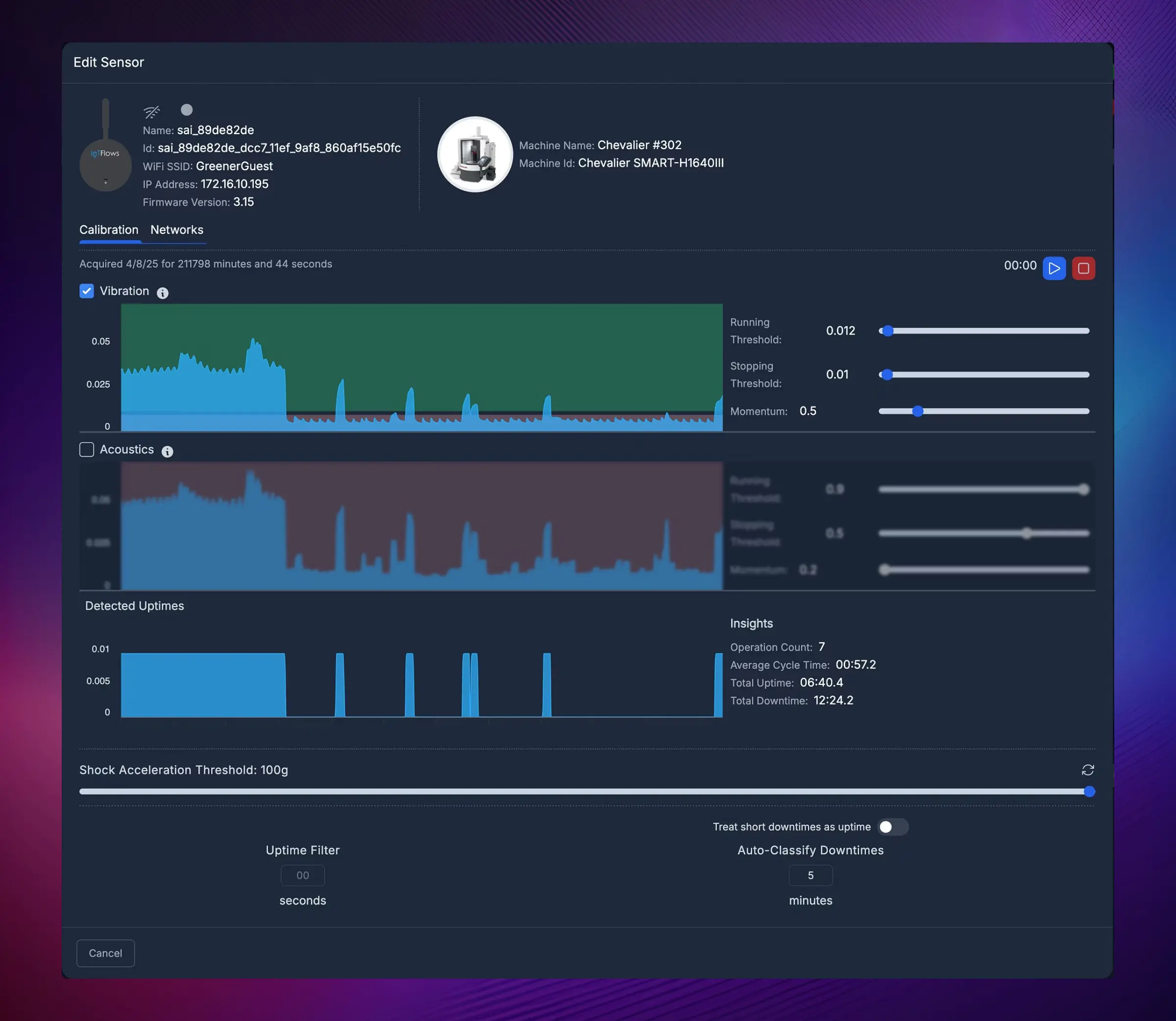
Step 2: Device Information & Status
The Calibration page displays key device and connection details:
- Sensor name and assigned machine
- Current and previous WiFi network
- IP and MAC address
- Firmware version
There are two tabs in this page:
- Calibration (default) — used for fine-tuning and sensor adjustments
- Networks — used only for switching networks (not for initial WiFi setup)
Step 3: Choose Detection Mode
Calibration Tab
Any adjustments made in this tab are reflected in real time on the connected device.
You can choose between:
- Vibration only (Recommended)
- Acoustics only
- Vibration + Acoustics
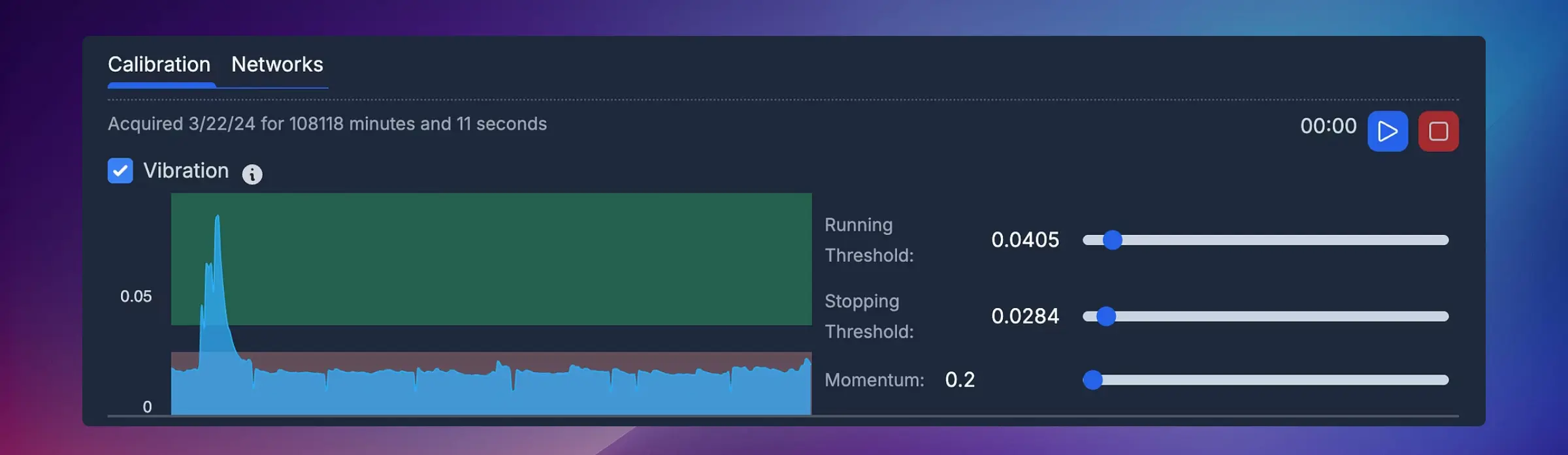
Step 4: Set Running/Stopping Thresholds
Live Data Streaming
-
Press the Play button (top right corner) to start real-time data streaming
-
You'll then see:
- Vibration levels (live)
- Acoustic intensity (if enabled)
- WiFi signal strength (for optimal antenna positioning)
-
Use this live view to observe:
- Idle vibration baseline — when the machine is ON but not cutting or working
- Running vibration baseline — when the machine is performing an operation
-
Once both states are observed, press Stop to stop data streaming
How to Interpret Live Data
Watch your machine go through both states:
- Let the machine sit idle (powered on, but not working) — observe the vibration level
- Start the machine working — observe the higher vibration level
- Note the clear difference between idle and running states
Setting Thresholds
Using the captured data:
- Set the Stopping Threshold slightly above the idle vibration level
- Set the Running Threshold slightly below the running vibration level of smoothest operation
How to adjust:
- Drag the slider handles, OR
- Type exact values in the input fields
What happens when you change thresholds:
- The Detected Uptimes graph recalculates to show how the new parameters affect uptime/downtime detection
- This chart is not live-updated — it refreshes after parameter changes or when you press Stop
Step 5: Configure Advanced Parameters
Momentum Parameter
The Momentum parameter defines how sensitive the sensor is to vibration changes.
- Higher momentum → slower response (more smoothing)
- Lower momentum → faster response (more sensitive)
Recommended values by machine type:
| Example Machine Type | Recommended Momentum |
|---|---|
| CNC / Laser | 0.2 – 0.5 |
| Press Brake | 0.05 – 0.1 |
When to adjust:
- CNC machines with gradual ramp-up: Use higher momentum (0.3-0.5)
- Press brakes with rapid on/off cycles: Use lower momentum (0.05-0.1)
- If you see rapid flickering between states: Increase momentum
- If detection is too slow to respond: Decrease momentum
Shock Acceleration Threshold
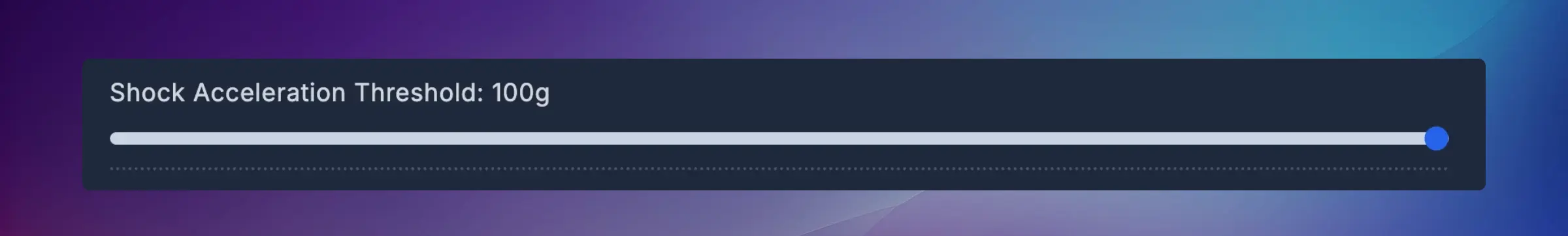
Set the Shock Acceleration Threshold to define at what vibration level the system should trigger a shock alert. This helps detect collisions, crashes, or abnormal mechanical impacts.
Use cases:
- Detect tool crashes in CNC machines
- Identify abnormal impacts or collisions
- Monitor machine health and wear
- Alert operators to potential damage
How to set:
- Observe normal operation shock levels during calibration
- Set threshold above normal operation but below concerning levels
- Test by creating a controlled impact (if safe to do so)
- Adjust as needed based on your requirements
Uptime Filter

The Uptime Filter helps clean up short, noisy uptimes caused by environmental vibration or operator movement.
How it works:
- Enter a value (in seconds) — e.g., 10s
- Any runtime shorter than that duration (in data older than ~30 minutes) is filtered out automatically

When to use:
- Machine has brief vibration spikes from nearby equipment
- Operators bump or touch the machine
- Environmental factors cause false detection
Recommended values:
- Most machines: 5-15 seconds
- Very stable environments: 3-5 seconds
- Noisy environments: 15-30 seconds
Downtime Threshold

Define a Downtime Threshold (in minutes), e.g., 5 minutes. This allows the platform to handle short downtimes in two ways:
Option 1: Auto-classify as "Short Downtime"
The algorithm looks back at the short pauses that happened more than 30 minutes ago and sets their downtime reason code as Short Downtime.

Option 2: Convert to uptime
The algorithm looks back at the short pauses that happened more than 30 minutes ago and converts them to runtime.

When to use:
- Auto-classify: You want to track all downtimes but automatically categorize quick pauses (e.g., tool changes, part loading)
- Convert to uptime: Short pauses are part of normal operation and shouldn't count as downtime (e.g., indexing time, brief cooldowns)
Organization Settings → Short Downtimes Assets Overview → Adjust Status Colors Calibration Validation
After completing calibration, validate that your settings are working correctly:
1. Test Both States
- Let the machine run for a few minutes
- Stop the machine and let it sit idle
- Check that the dashboard correctly reflects both states
2. Review Recent Data
- Look at the last hour of data on your dashboard
- Verify uptime/downtime matches actual machine operation
- Check for excessive false positives or negatives
3. Monitor Over Time
- Observe performance over the next 24-48 hours
- Look for patterns of mis-detection
- Adjust parameters if needed
Common Calibration Mistakes
❌ Setting thresholds too close together → Can cause rapid flickering between states
❌ Using momentum that's too low → Creates excessive state changes from minor vibrations
❌ Setting uptime filter before calibrating thresholds → Masks underlying calibration issues
❌ Not testing both idle and running states → Leads to incorrect threshold placement
✅ Best Practice: Make small adjustments and validate each change before proceeding to the next parameter.
Troubleshooting Calibration Issues
Thresholds Not Detecting Correctly
Problem: Machine shows as running when it's idle (or vice versa)
Solutions:
- Review your threshold settings — they may be set incorrectly
- Recollect live data during both idle and running states
- Ensure you're observing true idle (machine on but not working) vs. completely off
- Check mounting location — may not be picking up vibration properly
Inconsistent Detection (Flickering)
Problem: Machine status rapidly switches between running and idle
Solutions:
- Increase the Momentum parameter to smooth out detection
- Widen the gap between Running and Stopping thresholds
- Check for external vibration sources affecting the sensor
- Consider using Uptime Filter to remove brief false detections
Device Not Responding
Problem: Changes in calibration don't seem to take effect
Solutions:
- Verify device is online (check LED status)
- Refresh the dashboard page
- Wait 30-60 seconds for changes to sync
- Check internet connectivity
Summary
- ✅ SenseAi devices arrive precalibrated but benefit from fine-tuning per machine
- ✅ Use Vibration only for most machines
- ✅ Play and Stop control real-time data streaming
- ✅ Adjust Running/Stopping thresholds to define operational states
- ✅ Momentum, Shock Acceleration, and Uptime Filters refine detection accuracy
- ✅ Downtime Thresholds automate short downtime handling
- ✅ Always validate calibration by testing both machine states
Next Steps
After successful calibration:
- Monitor performance over the next 24-48 hours
- Review OEE reports to ensure accuracy
- Set up alerts for downtime or anomalies
- Fine-tune as needed based on actual operation
Continue learning:
Ready to get the most accurate data from your SenseAi? Remember: calibration is an ongoing process — adjust as your machine's characteristics change over time!