

Configure tracking for injection molding
Count parts on a machine whose shot cycle repeats to the second.
An injection molding machine runs the same cycle over and over: clamp, inject, hold, cool, eject. Continuous Analysis is the algorithm for that case: it divides running time by the cycle time you enter instead of hunting for one burst per part, which is what you want on a machine whose trace never falls back to the stopped level between shots. Allow 30 to 45 minutes for the first machine.
Before you start
- A SenseAi or SenseAi Embedded tied to the machine. Contact IoTFlows to tie your sensors to an asset, see Get support.
- Sign in as an Organization Owner or Organization Administrator, see Roles reference.
Why Continuous Analysis fits a molder
Four things about molding point at the same algorithm.
- The cycle time is known and it repeats. Every shot takes about the same time, so dividing running time by that number is accurate.
- The pauses are short. Mold open, ejection and mold close interrupt the trace for a second or two and should not read as stops.
- The volume is high. Hundreds or thousands of shots a day, so a detector that misreads one burst in fifty is wrong by hundreds of parts.
- The rhythm is steady. Once the machine is at temperature it holds the same cycle until something interrupts it.
You do not need a second sensor to count parts. SenseAi derives part counts and cycle times from the same vibration trace that produces the running and stopped state.
Choose Discrete Analysis instead when the machine waits between shots. A molder where an operator loads inserts by hand, or takes parts off before the next cycle starts, looks more like a machining center than a molder to the sensor.
Mount the sensor on the machine
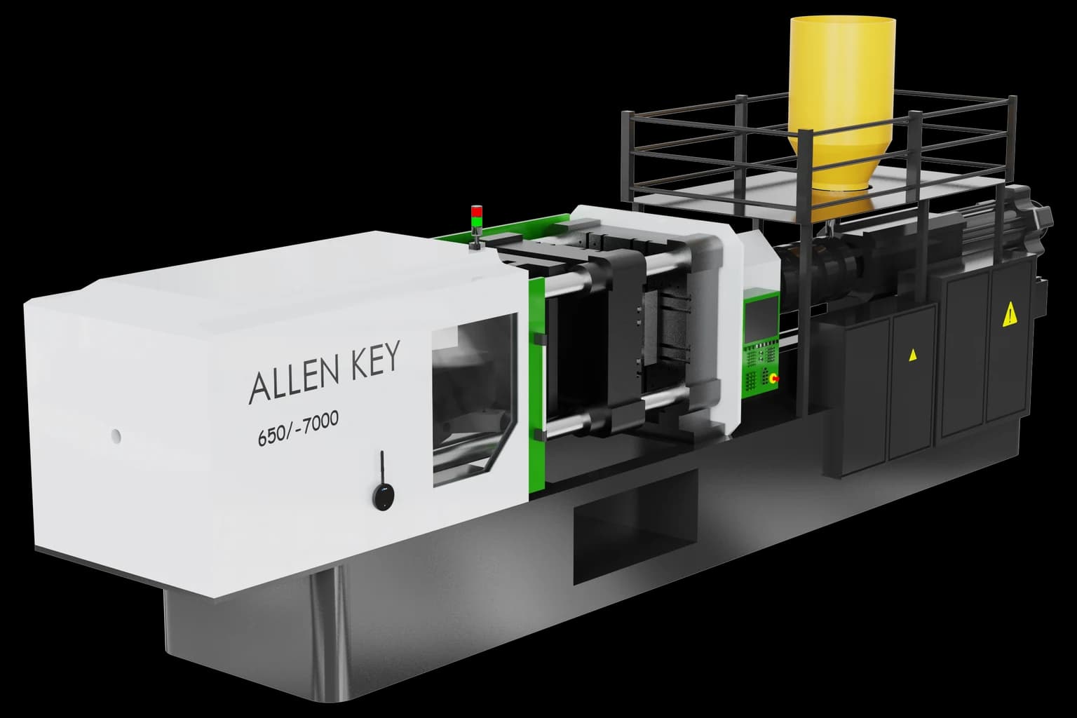 A horizontal injection molding machine. The injection unit and the hydraulic power unit, on the right of the machine, both carry the cycle.
- Mount on flat ferrous metal close to the injection unit or the hydraulic pump. Both work through every shot, so both carry the cycle.
- Do not mount on a guard, a cover or a sheet-metal panel. The magnet holds, and what the device reads is the panel's own ringing rather than the machine's, see Choose a mounting location.
- Stay clear of the barrel and its heater bands. SenseAi Embedded is rated to 60 °C (140 °F), and a barrel zone runs far past that.
- Connect power and put the device on Wi-Fi, see Connect a device to Wi-Fi.
- Run 10 or more complete shots while you calibrate, so the thresholds are set against a molding cycle and not against a dry cycle or a warm-up, see Calibrate SenseAi and SenseAi Embedded.
Verify the mount rather than judging it by eye. Run the machine molding, then stop it, and confirm the two read differently.
Measure the shot cycle
Continuous Analysis divides running time by this number, so the accuracy of the number is the accuracy of the count. Measure it, do not take it off the machine's setup sheet.
- Let the machine run normally until it settles at temperature.
- Time 10 consecutive shots with a stopwatch, from shot start to shot start.
- Average them. For example, 22, 21, 23, 22, 21, 22, 23, 22, 22 and 22 seconds average to 22 seconds.
- Note the pauses between shots as well. In molding they usually run 1 to 5 seconds, and they are what the downtime filter is for.
Time the shot, not the part. On a multi-cavity mold one shot makes several parts, and the cavity count is set separately on the operation.
Create the part and its operation
- Open Parts List at
/production?select=parts_list. - Click + Add Part.
- Enter a Part Name, for example
Automotive Clip. Part Description is optional. - Under Assign Operations, name the operation after the mold, for example
MOLD-CLIP-4CAV, and describe it, for example4-cavity mold, black ABS. - Enter Operation Cycle Time in the h, m and s boxes. For a 22-second shot, that is 22 in the s box.
- Enter a standard deviation in the boxes beside it. Leaving either at zero blocks the part with Cycle time and standard deviation must be greater than zero.
- Add the machines that run this operation, then click Add Part.
- Back on the Parts List, expand the part, click the operation's Algorithm cell and choose Continuous Analysis. It saves as you pick it.
- Set QTY/OP to the number of cavities in the mold. A four-cavity mold is 4.
Quantity per cycle is the parts one cycle makes, so on a molder it is the cavity count. A four-cavity mold running 100 shots made 400 parts, and the same mold left at 1 reports a quarter of its real output. Full field reference on Create parts and operations.
Create one operation per mold, not one per part number. If you run the same clip in a two-cavity and a four-cavity mold, the cavity count differs, so the two need separate operations: MOLD-CLIP-2CAV and MOLD-CLIP-4CAV.
Set the downtime filter
A downtime filter converts any stop shorter than a set percentage of the cycle time into uptime, so brief in-cycle pauses stop reading as stops. It is the one field only Continuous Analysis has: the Downtime Filter column appears on the Parts List once the part carries a continuous operation, and nowhere else.
- On the Parts List, expand the part.
- Click the operation's Downtime Filter cell and type a percentage.
- Press Enter or click away. It saves on blur.
The field takes 0 to 200% and clamps anything higher. 200% is the recommended starting point for a molder. On a 22-second cycle that converts every stop under 44 seconds into runtime, leaving the real interruptions in the downtime record: material shortages, mold problems, an operator stopping the machine.
Check that 44 seconds against your own stops before you accept it, because a 40-second material hiccup now reads as production. If stops in that range are worth seeing, come down. At the same cycle, 50% still covers an 11-second pause, which is twice the longest mold open.
You do not need a filter on a machine whose pauses never reach the downtime record. Leave the field empty, run a shift, and read the Downtimes report first. A filter set on a machine that has no short pauses only hides its real ones.
Assign the operation to the machine
- Open Assets at
/assetsand click the machine. - Click Auto-Detect to open Select Auto-Detect Operations.
- Open the Continuous tab. A SenseAi machine shows the Discrete and Continuous tabs only, because Counter is BeamTracker's algorithm.
- Select the operation's radio button. This list is single choice, not checkboxes.
The dashboard saves as you pick, confirms with Continuous Auto-Classification Set and closes the modal. There is no submit button on this tab, only Close. To stop detection without choosing another operation, select No Continuous Detection.
Selecting a continuous operation clears any discrete operation the machine was set to, and the modal says so above the list. The full flow, including detected cycle times and the Parts List entry point, is on Detect operations automatically.
Handle mold and material changes
Because the Continuous tab is single choice, a molder carries one operation at a time. A mold change is two jobs: swap the mold, then re-pick the operation. Skipping the second counts the new mold's shots against the old mold's cycle time and cavity count, which is the most common reason a molder's numbers go wrong after a changeover.
A color or material change is different. Same mold, same operation, nothing to re-pick, and 15 to 30 minutes of downtime worth seeing rather than absorbing.
- Create a Material Change category, see Create a category. Add Mold Change while you are there.
- Have operators classify the stop when it happens, see Classify a downtime event.
- If changeovers are frequent and always look the same, write a rule so they classify themselves, see Classify downtime automatically.
- After two to four weeks, read the total off the Pareto chart on the Downtimes report.
Validate the count
- Let the machine run normally for one to two hours.
- Open Shift Production at
/production?select=partand read the count for the operation. - Work out what it should be. One hour of running time is 3,600 seconds, so at 22 seconds a shot that is 163 shots, and a four-cavity mold makes 652 parts.
- Compare the two. Within 5 to 10% is right.
- Open Downtimes at
/assets?select=downtimesand confirm real stops are recorded while mold-open pauses are not filling the list.
Accuracy bands and what to do at each one are on Choose a production tracking algorithm.
What to expect from a molder
Uptime is availability: the share of the window the machine spent running, see Uptime. How much of the cycle a person carries sets the ceiling, so a machine an operator tends and a lights-out cell are not comparable.
| How the machine runs | Uptime to expect |
|---|---|
| An operator loads inserts or takes parts off | 60 to 75% |
| Fully automatic, nobody in the cycle | 75 to 85% |
| Lights-out, running unattended around the clock | 85 to 90% |
Set the goal on Set OEE and utilization goals. Start from your own baseline plus 5 to 10%, not from the table. A goal the machine has never met teaches operators to ignore the number.
If the process has a quality check, log rejects separately so the good count is the number you compare, see Log scrap.
Troubleshoot a molder
| Symptom | Cause | Fix |
|---|---|---|
| Count runs high | The downtime filter is converting real stops into runtime | Lower Downtime Filter, then check the Downtimes report for the stops that reappear |
| Count runs low | Mold-open pauses are recorded as downtime, so running time is short | Raise Downtime Filter. At 200% you are at the ceiling, so set Downtime Threshold with Treat short downtimes as uptime instead, see Handle short stops |
| Count is a fixed fraction of real output, and the fraction matches the mold | QTY/OP is still 1 on a multi-cavity mold | Set QTY/OP to the cavity count. The count corrects immediately |
| Count is off by the same ratio all shift, and changing the filter does nothing | The entered cycle time no longer matches the shot | Re-time 10 shots and update Ideal Operation Cycle Time on the Parts List. Continuous Analysis divides by it, so the count is only as good as that number |
| Numbers went wrong at a changeover and stayed wrong | The operation was not re-picked, so shots are counted against the previous mold | Re-pick the operation on the Continuous tab, see Assign the operation to the machine |
| Uptime reads low on a shift the machine ran through | The running threshold sits above the molding trace, so part of the cycle reads as stopped | Lower the Running Threshold, see Set the running and stopping thresholds |
| The downtime list fills with one-minute stops | Pauses the operation's filter does not reach are still recorded | Set Downtime Threshold with Treat short downtimes as uptime on, see Handle short stops |
Counts that stay wrong after the cycle time and the filter are both right are on Troubleshoot inaccurate part counts.
See it in a plant
See also
From the blog
- What utilization to expect by machine typeA manual CNC runs 40–60% of the shift, a coil-fed press 65–80% and a lights-out cell 80–90%. See why loading sets the ceiling and how to set each goal.
- How to monitor injection molding machinesCount shots, multiply by working cavities and keep mold-open pauses out of downtime. Learn why a molder's count reads double or half, and how to check it.
Set up part counting on a machining center whose cycle time changes with the part. Mount the SenseAi near the spindle, measure a typical cycle by hand, create the part with one operation per thing the machine does, set the operation's algorithm to Discrete Analysis, then assign every operation the machine runs to it at once from the Auto-Detect modal's Discrete tab, which is multi-select. Validate against a hand count, expect 40 to 85% uptime depending on how much of the cycle an operator carries, and read setup time out of the Downtimes report.
Set up stroke counting on a press that fires 10 to 120 times a minute. Mount the SenseAi on the frame near the ram, measure the stroke rate, create the part with one operation per die, set the operation's algorithm to Discrete w/o Merge, then assign every die's operation at once from the Auto-Detect modal's Discrete tab, which is multi-select. Because nothing is merged, every gap between strokes reaches the downtime record until you set the machine's Downtime Threshold with Treat short downtimes as uptime switched on. Operation Cycle Time takes whole seconds, so a press faster than 60 strokes per minute cannot carry an exact cycle time and its shift goal is approximate.