

Configure tracking for stamping and punch presses
Count strokes on a machine that fires tens of times a minute.
A stamping or punch press makes one part per stroke, and each stroke is a sharp impact the sensor can see on its own. Discrete w/o Merge is the algorithm for that case: it counts every burst it detects and merges nothing, so two strokes a second apart stay two parts. Allow 30 to 45 minutes for the first press.
Before you start
- A SenseAi or SenseAi Embedded tied to the press. Contact IoTFlows to tie your sensors to an asset, see Get support.
- Sign in as an Organization Owner or Organization Administrator, see Roles reference.
Why Discrete w/o Merge fits a press
Four things about a press point at the same algorithm.
- Every stroke is a separate event. The ram hits, and that impact is the part.
- The strokes come fast. A press runs 10 to 120 strokes per minute, so any rule that merges nearby events merges real parts.
- One stroke is one part. Nothing has to be reassembled from several bursts, which is the job merging exists to do.
- The gaps between strokes are brief. They belong to the rhythm rather than to the downtime record, and they are handled on the machine instead of in the algorithm.
You do not need a second sensor to count strokes. SenseAi derives part counts and cycle times from the same vibration trace that produces the running and stopped state.
Choose Discrete Analysis instead when the press rings more than once per stroke. Impact and rebound on a heavy mechanical press can read as two events, and Discrete Analysis merges the second back into the cycle. A count that runs at exactly double the real output is that problem and nothing else.
Mount the sensor on the press
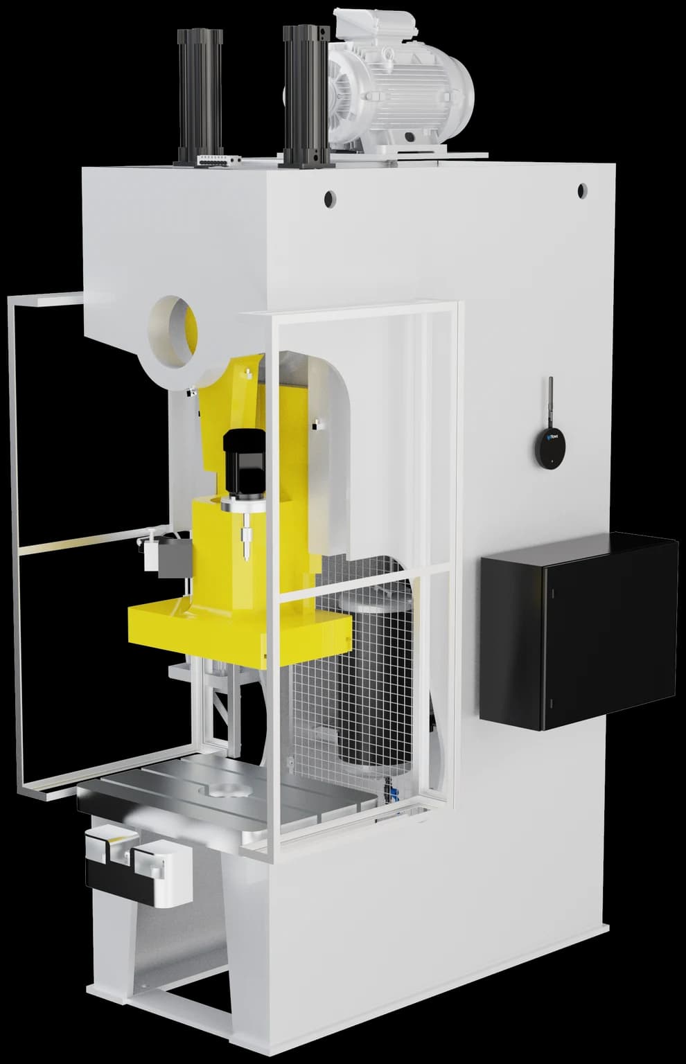 SenseAi on a press, mounted on the frame beside the ram rather than on a guard.
- Mount on the frame as close as you can get to the ram or the drive, where the stroke is strongest.
- Pick flat ferrous metal that is mechanically part of the press. A guard or a sheet-metal panel holds the magnet and passes on its own ringing rather than the driveline's, see Choose a mounting location.
- Connect power and put the device on Wi-Fi, see Connect a device to Wi-Fi.
- Run 10 or more strokes in production while you calibrate, so the thresholds are set against real strokes rather than a dry cycle, see Calibrate SenseAi and SenseAi Embedded.
Verify the mount rather than judging it by eye. Run the press, then stop it, and confirm the two read differently.
Count at the part exit instead
A BeamTracker at the exit chute counts parts leaving the press rather than strokes happening inside it. It runs the Counter algorithm, which takes each break of its beam as one cycle.
Choose a BeamTracker at the exit when:
- The press rings more than once per stroke and no threshold separates the rings cleanly.
- You want the count to be parts that cleared the die, not strokes that may have misfed.
- The press is one station of a line and the count you report on belongs to the line.
A BeamTracker is a calibration job rather than an algorithm choice. Set what the beam treats as a part in Set what counts as a part, and set how long the line stays running after the last part in Set the downtime filter. That filter lives on the device and is measured in seconds.
You do not need a BeamTracker if the SenseAi count already validates. A second device is a second thing to calibrate.
If you go this way, the full Counter setup is on Configure tracking for bottling and packaging lines, which covers the same algorithm on any line of units passing a point.
Measure the stroke rate
- Run the press normally for 5 minutes and let it settle.
- Count strokes for one full minute, off the press counter if it has one. For example, 45 strokes in a minute is 45 SPM.
- Divide 60 by that number to get the cycle time. At 45 SPM, 60 ÷ 45 is 1.33 seconds per stroke.
- Note the pauses between strokes as well. On a press they run from a fraction of a second to a second or two, and they are what the machine's short-stop setting is for.
Operation Cycle Time takes whole seconds. The h, m and s boxes are number fields read as integers, so 1.33 is stored as 1 and there is no sub-second entry. Discrete w/o Merge does not read the cycle time to count, so the count is unaffected. The shift goal and the parts gauge do read it, so round to the nearest whole second and treat the goal as approximate unless the stroke rate divides into 60 evenly, as 60, 30, 20, 15 and 12 SPM do.
Create the part and its operation
- Open Parts List at
/production?select=parts_list. - Click + Add Part.
- Enter a Part Name, for example
Steel Bracket. Part Description is optional. - Under Assign Operations, name the operation after the die, for example
STAMP-BRACKET-100T, and describe it, for example100-ton press, progressive die. - Enter Operation Cycle Time in the h, m and s boxes. For a 1.33-second stroke, that is 1 in the s box.
- Enter a standard deviation in the boxes beside it. Leaving either at zero blocks the part with Cycle time and standard deviation must be greater than zero.
- Add the machines that run this operation, then click Add Part.
- Back on the Parts List, expand the part, click the operation's Algorithm cell and choose Discrete w/o Merge. It saves as you pick it.
- Set QTY/OP to the parts one stroke makes. On a press this is almost always 1.
Quantity per cycle is the parts one cycle makes. A progressive die carries a part through several stations per stroke and still finishes one part per stroke, so it is 1, the same as a single-hit die. Raise it only for a multi-out die that drops more than one part per stroke, see Create parts and operations.
Create one operation per die, not one per part number. The table shows no Downtime Filter column here: that column belongs to Continuous Analysis alone, so a Discrete w/o Merge operation has nothing to leave blank.
Handle the gaps between strokes
Because nothing is merged, every gap between strokes can reach the downtime record, and a shift turns into hundreds of one-minute rows nobody can classify. The fix sits on the machine, not on the operation. Two layers do two different jobs:
| Layer | Where you set it | What it does |
|---|---|---|
| Algorithm | The operation, on the Parts List | Discrete w/o Merge counts every detected burst as one stroke |
| Short-stop handling | The machine, on the sensor's Calibration tab | Converts any stop under the cutoff into runtime before it reaches the report |
Set the second layer from Downtime Threshold with Treat short downtimes as uptime switched on, see Handle short stops. The field is in minutes. With the toggle off, the same field is labeled Auto-Classify Downtimes and short stops stay in the record with a reason code instead of disappearing.
| Press type | Strokes per minute | Downtime Threshold | Why |
|---|---|---|---|
| High-speed stamping | 60 to 120 | 10 to 15 minutes | Removes brief pauses and leaves only major stops |
| Medium-speed punching | 30 to 60 | 5 to 10 minutes | Balances detail against noise |
| Low-speed forming | 10 to 30 | 3 to 5 minutes | Slower work needs more sensitivity |
| Manual feed presses | Varies | 2 to 5 minutes | Keeps operator pauses visible |
Read the threshold as a decision about what you are willing to stop seeing. A 10-minute threshold converts a 9-minute material jam into runtime, so it is also a statement that 9-minute jams are not worth reporting. Start at the low end of the band, run a shift, then raise it only if the Downtimes report is still full of pauses nobody can act on.
Assign the operation to the machine
- Open Assets at
/assetsand click the press. - Click Auto-Detect to open Select Auto-Detect Operations.
- Stay on the Discrete tab, which holds both discrete algorithms. A SenseAi machine shows the Discrete and Continuous tabs only, because Counter is BeamTracker's algorithm.
- Check every die's operation that this press runs. The list is checkboxes, not a single choice.
- Click Auto-Detect. The dashboard confirms with Discrete Auto-classification Set.
Because the tab is multi-select, assign every die the press runs at once and leave them assigned. A die change then needs nothing on the dashboard, and each die's output is reported separately, see Compare production over weeks and months.
Selecting discrete operations clears any continuous operation the machine was set to, and the modal says so above the list. The full flow is on Detect operations automatically.
Track die changes and material loading
A die change is the largest single stop on most presses, and it is invisible until stops carry reasons. A typical one runs 15 to 60 minutes, so it clears any threshold in the table above.
- Create a Die Change category, see Create a category. Add Setup / Adjustment for the fine-tuning after the die is in.
- Add Material Loading as well. Coil loading takes 5 to 10 minutes, so keep Downtime Threshold at or below 5 minutes if you want those stops in the record at all.
- Have operators classify the stop when it happens, see Classify a downtime event.
- If changeovers always look the same, write a rule so they classify themselves, see Classify downtime automatically.
- After two to four weeks, read the totals off the Pareto chart on the Downtimes report.
Validate the count
- Let the press run normally for one to two hours.
- Open Shift Production at
/production?select=partand read the count for the operation. - Work out what it should be. A press at 60 SPM running for 60 minutes made 3,600 strokes.
- Compare the two. Within 2 to 3% is right on a press, which counts more precisely than a machine whose cycles have to be inferred from a varying trace.
- Open Downtimes at
/assets?select=downtimesand confirm real stops are recorded while the gaps between strokes are not filling the list.
Accuracy bands and what to do at each one are on Choose a production tracking algorithm.
What to expect from a press
Uptime is availability: the share of the window the machine spent running, see Uptime. How the material reaches the die sets the ceiling, so a hand-fed press and a coil-fed one are not comparable.
| How the press runs | Uptime to expect |
|---|---|
| Manual feed, operator places every blank | 50 to 65% |
| Auto feed from coil | 65 to 80% |
| Lights-out automation | 80 to 90% |
Set the goal on Set OEE and utilization goals. Start from your own baseline plus 5 to 10%, not from the table. A goal the press has never met teaches operators to ignore the number.
Watch the stroke rate over time as well as the total. A rate that drifts down points at tooling wear, and downtime that climbs while the rate holds points at material, see Compare production over weeks and months.
Troubleshoot a press
| Symptom | Cause | Fix |
|---|---|---|
| Count is double or triple the real output | The press rings on impact and again on rebound, and nothing merges the second ring | Switch the operation to Discrete Analysis, which merges it, see Switch to a different algorithm |
| Count is slightly low | Gentle strokes sit below the running threshold | Lower the Running Threshold, then move the sensor closer to the ram and check for metal-to-metal contact, see Set the running and stopping thresholds |
| The downtime list fills with one to five minute stops | Downtime Threshold is below the press's own rhythm | Raise it, and confirm Treat short downtimes as uptime is on, see Handle short stops |
| Real stops are missing from the record | Downtime Threshold is above the stops you care about | Lower it. At 5 minutes, coil loading reappears |
| The shift goal does not match the strokes the press makes | The cycle time was rounded to a whole second | Expected on any press that does not divide into 60 evenly. Compare against a stroke count rather than the goal, see Measure the stroke rate |
| Uptime reads low on a shift the press ran through | The running threshold sits above the trace between strokes, so the gaps read as stopped | Lower the Stopping Threshold and raise momentum, see Set the running and stopping thresholds |
Counts that stay wrong after the algorithm and the thresholds are both right are on Troubleshoot inaccurate part counts.
See it in a plant
See also
From the blog
- What utilization to expect by machine typeA manual CNC runs 40–60% of the shift, a coil-fed press 65–80% and a lights-out cell 80–90%. See why loading sets the ceiling and how to set each goal.
- How to monitor an old machine with no network portA sensor on the frame reads running, stopped and every cycle from outside, so a 30-year-old machine with no port reports uptime and part counts like a new one.
- Do micro-stops count as downtime?Micro-stops are downtime, but standard OEE definitions book them as a performance loss. See where they land, why OEE holds steady and how to set the cutoff.
Set up part counting on an injection molding machine, whose shot cycle repeats to the second. Mount the SenseAi on the injection unit or near the hydraulic power unit, time 10 to 20 shots by hand, create the part with one operation per mold, set the operation's algorithm to Continuous Analysis, set QTY/OP to the cavity count, and set the Downtime Filter so brief mold-open pauses do not read as stops. The filter takes 0 to 200%. The Continuous tab of the Auto-Detect modal is single choice, so the machine carries one operation at a time and you re-pick it at every mold change.
Set up part counting on a line whose output is units moving past a point: bottles, cans, packets, tubes, cartons or cases. Mount a BeamTracker across the part path after the last reject point, set the operation's algorithm to Counter, name the unit in OP UNIT so gauges read bottles/min, and set QTY/OP to 1 when the beam sees each unit or to the pack count when it sees a case. A Counter operation's cycle time feeds goals and the rate, never the count, and the downtime filter lives on the device in seconds rather than on the Parts List as a percentage. The Count tab of the Auto-Detect modal is single choice, so the line carries one operation at a time and you re-pick it at every product change.